Pipeline trenching is the normal practice for every pipeline that has been used for the tranportation of oil and gas product from the offshore facility to the onshore facility especially in countries where the water depth is shallow like Malaysia. Trenching are made to protect the pipeline from exposure to any danger that will cause any damage to the pipeline like ship's anchor drag on the seabed. Discussed below is the principle and the procedure related to the post-lay pipeline trenching of an underwater pipeline.
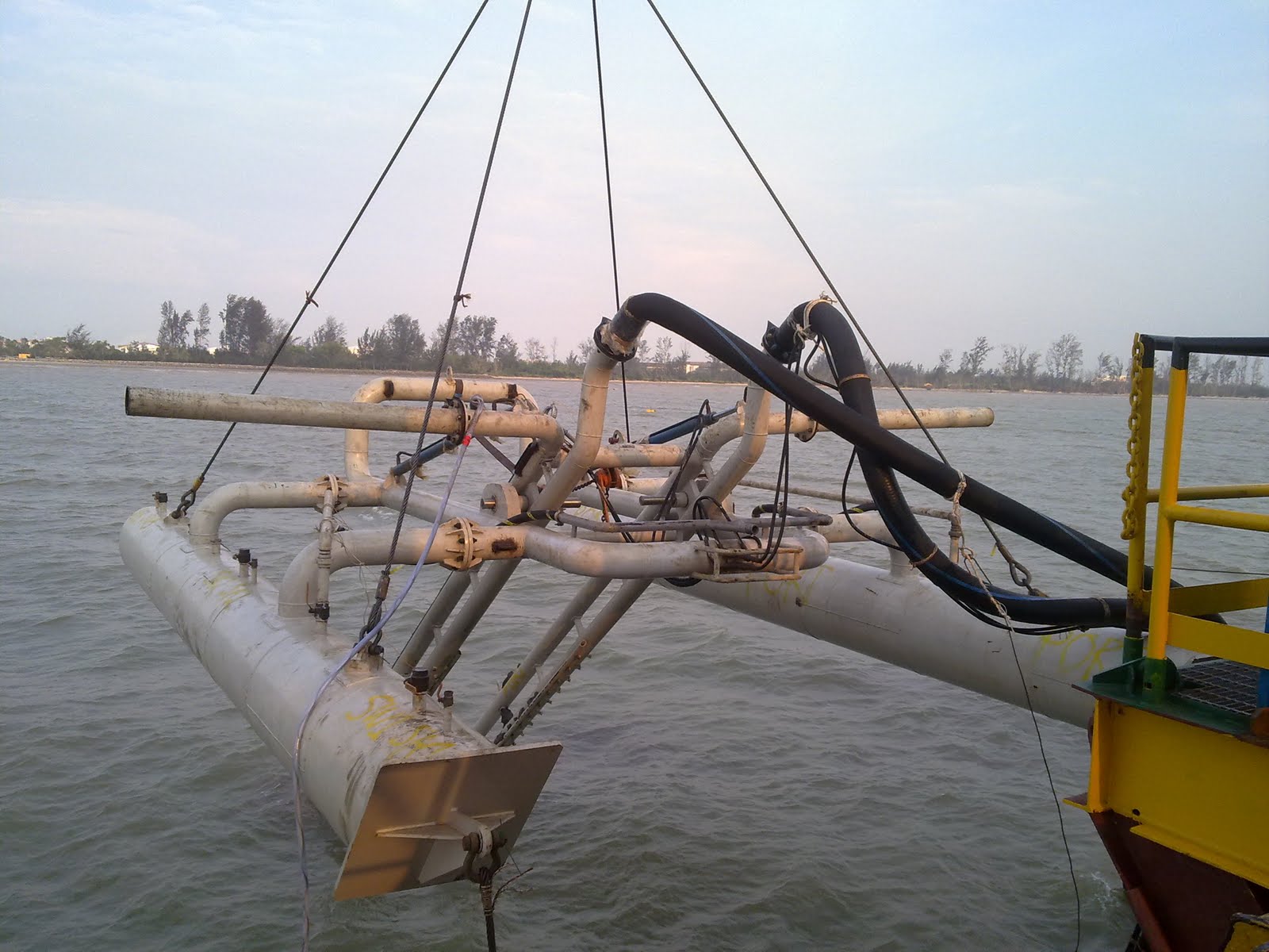 Figure 1: Trencher Machine - Commerce 1
 Figure 2: Commerce 1 under Testing
PRINCIPAL OF TRENCHING
The principle of trenching is to create a trench beneath an existing pipeline so that the pipeline will be lowered down into the seabed. The basic steps of trenching are:
The principle of trenching is to create a trench beneath an existing pipeline so that the pipeline will be lowered down into the seabed. The basic steps of trenching are:
- Hydraulically driven mechanical cutter create two slot on both side of the pipeline.
- Jets and eductors that are located behind the cutters will fit into the slots created.
- Cutters will pave the way for the trenching machine to move forward.
- Cutters will allow jet energy to be concentrated underneath the pipeline in a hard type of clays and underneath and also the side of the pipeline in soft and cohessionless type of soil.
- Jet manifold incorporates nozzle to direct pressurized water to cut soils underneath and to the side of the pipeline.
- Certain nozzles will be used depending on the type of soils and also the shape of the trench.
- Eductors are used to remove the cut and liquefied soils from the trench and deposit soil to the side of the trenching machine. Eductors are powered by the pressurized water.
ONSHORE AND OFFSHORE SITE PREPARATION
On shore, the Real Time Kinematic (RTK) contorl referance station will be set up, calibrated and fully operational prior to the arrival of the trenching barge at the location while divers will mark the pipeline around the starting location buoys so that it will serve as the visual marker for the barge during setting up at the intended location. The marking shall be completed before the arrival of the trenching barge.
 Figure 3: Working Barge POE Giant 7
SETTING AND ANCHORAGE OF BARGE FROM THE START POINT
- Trenching barge will be towed at the intended location and will be set up approximately 60m from the trencher location.
- Upon arrival at the visual marked buoy location set up earlier by diver and assisted by the survey team, towing bridle will be switched to anchor cable #1 for final approach and shallow water Anchor Handling Tug (AHT) will deploy anchor #1 at the intended location.
- The barge will be repositioned close to the shore with the assistance of a tug boat and the utility boat will deplo mooring anchor #3.
- Shallow water AHT will run anchor #4 and the utility boat will deplot anchor #2 close to the shore. After all the anchor have been deployed barge will be repositioned at intended start-up location.
TRENCHING MACHINE BALLAST TANK
Every trenching machine has its own ballast tank for the purpose of buoyancy to provide acquired depth of trenching depth for every trenching operation. There are some procedures that are usually being practised by the trenching superintendant to float and also to sink the trenching machine for the purpose of the trenching operation.

<>Ballasting Procedure
- Attach the 2" air and water supply hose to trencher intake line.
- Make sure 3 of the 2" in line ball valve at left side and 3 at the right side in open position.
- 3 of the 2" drain ponits ball valve at left side and 3 at the right side in close position.
- 3 of the 1" air vent point ball valve at lesft side and 3 at the right side in open position.
- Close the 1" air supply ball valve at main manifold.
- Open the 2" water supply ball valve slowly to allow water flow to buoyancy tank.
- Fill-up activities completed when the water flow out at 6 points of the 1" air vent points.
- Close the 2" air and water supply ball valve.
- Disconnect the 2" air and water supply hose from trencher.
- Close all 6 of the the 1" air vent point.
- Trencher ready to lower down to sea bed by crane.
- Attach the 2" air and water supply hose to the trencher intake line.
- Make sure 3 of the 2" in line ball valve at left side and 3 at right side in open position.
- 3 of the 2" drain points ball valve at left side and 3 at right side in close position.
- 3 of the 1" air vent point ball valve at left side and 3 at right side in close position.
- The 2" water supply ball valve in close position (open manifold).
- Open the 1" air supply ball valve slowly to allow air flow to buoyancy tank.
- Drain out water completed when the air flow out at 6 points of the 2" drain point.
- Close the 2" air supply ball valve.
- Disconnect the 2" air and water supply hose.
- Close 6 of the 2" drain point ball valve.
- Trencher ready to lift up by crane to the barge.
- The deployment of the trencher machine will be assisted by diver. Once the divers are back on board the work barge, the Superintendent will then commence the full function test of the trenching system.
- Surveyor will then fine the tune of the Dual Profile to ensure the data obtain from the both profiles are synchronised.
- Trenching operation will stop after completion of initial 20 meters to allow divers to inspect the status of the trench and to adjust the nozzle if required.
- The Intergrated Trenching System will go online and ready to resume the trenching operations.
- The jetting pumps will be restarted and the trenching work will be fully operated. The commencement and relevant monitoring of the trenching operations will be overseen by the trenching superintendent.
- Diver inspection will be conducted regularly for every 30 meter of trenching to monitor the pipeline and the trench profile as required for the operations. This shall be done by using the pole and feel method to confirm the trench depth.
excelletn info, i am looking for such a machine, can i be contacted on rahulgonsalves@hotmail.com, where we cant ake this discussion ahead, and be optimistic of some sucessful business. thanks Joseph gonsalves
ReplyDeleteHello,
ReplyDeleteThanks for sharing innovative info.A trench is a type of excavation or depression in the ground that is generally deeper than it is wide (as opposed to a wider gully or ditch), and narrow compared to its length (as opposed to a simple hole).Non Explosive Cracking Agent
HVS When your website or blog goes live for the first time, it is exciting. That is until you realize no one but you and your.
ReplyDelete